![]()
![]()
TEPCO has a wide variety of tools and simulating softwares to assess environmental impacts associated with construction of transmission facilities. For example the three dimensional graphic CAD is giving a clear virtual landscape after the completion of structure construction. This is quite helpful in recognizing virtually how well matched the newly constructed facilities can be harmonized with surrounding environment and what can be the best alternative route for transmission lines. The dynamic response analyzing software for overhead lines will give clear guarantee on whether or not design strength meet the required levels for harsh weather conditions.
TEPCO has also developed system simulator software to evaluate the effects of line/equipment contingency in terms of entire system reliability and local overloading on lines, transformers and other serial switchgears.
They are the services offered by TEPCO to help utilities to produce optimum design and plans for both construction and network structuring.
Transmission Network
Planning
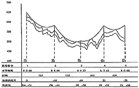
Plane Diagram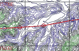
![]()
![]()
© Tokyo Electric Power Company Holdings, Inc.